12:48:00 PM
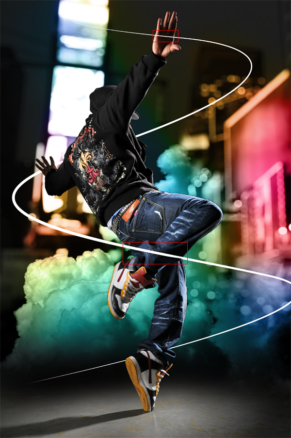
In this detailed and lengthy Photoshop tutorial, you will learn how to combine photos and add special effects to turn a normal photograph into a stunning artwork. You will also learn several tricks to reduce your Photoshop document file size and number of layers and layer styles.
Dazzling Dance Photo Manipulation Photoshop Tutorial
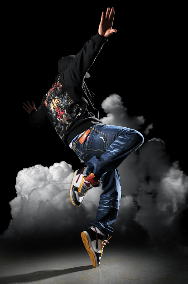
Preview of Final Results

Stock Photos
Here are the stock photos used for this website. You can purchase the images through Dreamstime by clicking on the image below. We used the highest resolution (unscaled) images available to write this tutorial. If you would like to follow this tutorial using the same settings we used, download the highest resolution (unscaled) images available.


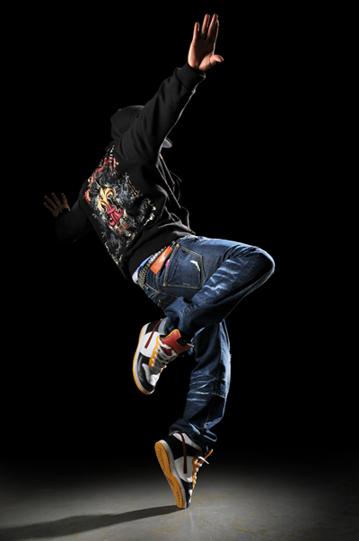
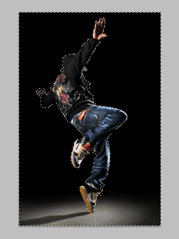
Step 1 – Open the image of the dancer
Load the image of the dancer into Photoshop.
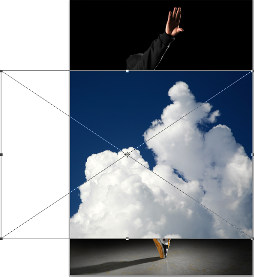
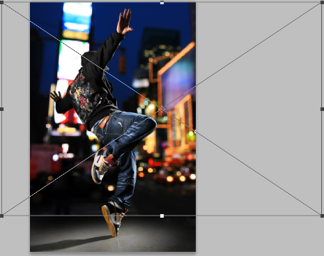
Step 2 – Place the image of the clouds
Choose File > Place, browse for the image of the clouds, then click OK. The image of the clouds will appear in your document window with the transform tool activated. Resize and position the clouds where you like it to appear then press enter on your keyboard to apply the changes. The reason why we use the place command rather than other methods is because the place command will place the image as a smart object (if you are using Photoshop CS2 or newer) to help keep the file size small if you save the document without the maximize compatibility option.
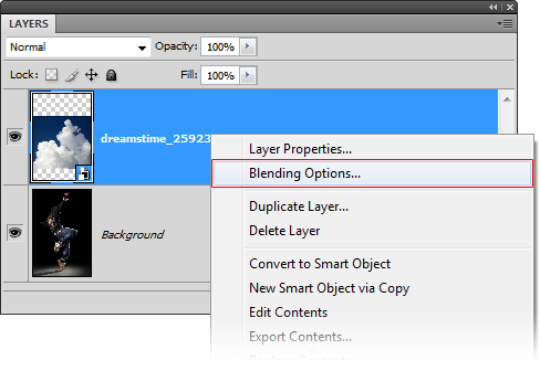
Step 3 – Blend the clouds
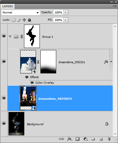
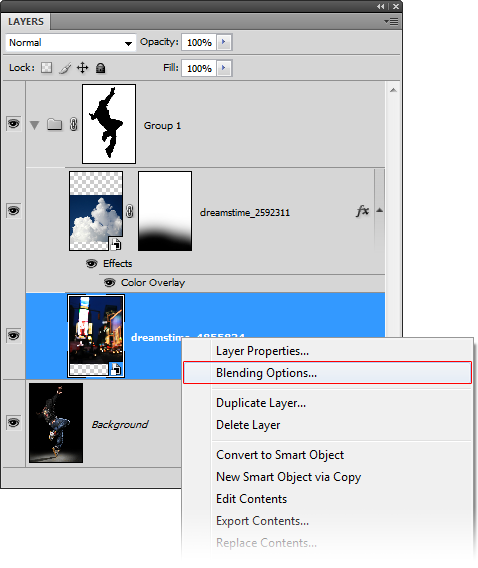
Now we’ll make the sky transparent so that only the clouds are visible. Instead of using a mask, we’ll use the blending options. This will help keep the file size small and reduce the number of layers in your document. Right click on the layer of the clouds then choose Blending Options.
In the blending options, move the black input slider towards the right until the sky disappears.
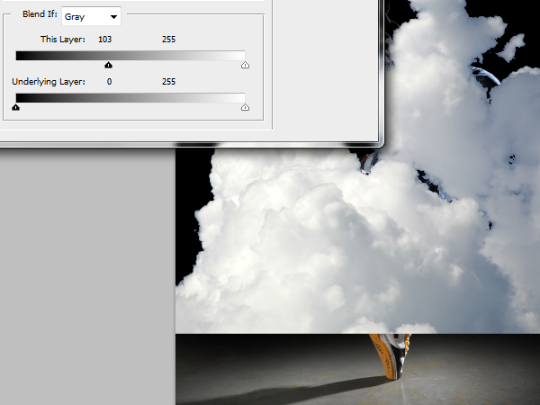
Hold the alt key on your keyboard and drag the black input slider all the way towards the right. The hard edges of the clouds should disappear and the clouds should have some transparency. Don’t click OK yet.
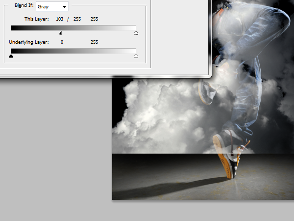
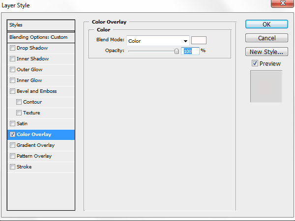
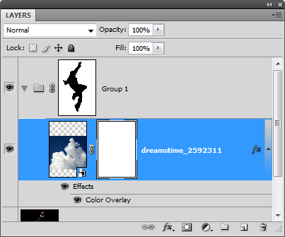
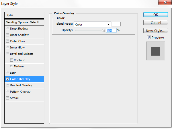
In the same layer style window, click on the Color Overlay option. Choose white as the color then set the blend mode to color. This is a simple non-destructive trick to desaturate a layer using layer styles. Click OK to apply the changes.
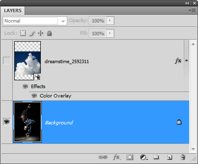
Here’s what the image looks like right now. You have just blended the cloud into the background without using any layer masks. We’re not 100% complete with blending the clouds in but we’re going to pause here and continue after we create a mask of the model.

Step 4 – Create an inverse selection of the model
Hide the layer with the clouds then select the background layer.
Select the magic wand tool then set the tolerance to 0 so that the black sweater won’t be included in the selection.

Click on the black area to create a selection of the background. You’ll get most of the background selected.
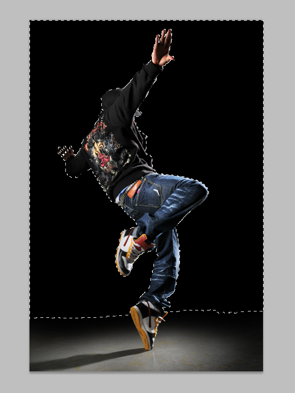
You can continue to add to the selection using the lasso tool. Or, if you’re using Photoshop CS3 or newer, switch to the quick selection tool, to easily add the bottom of the background into the selection.
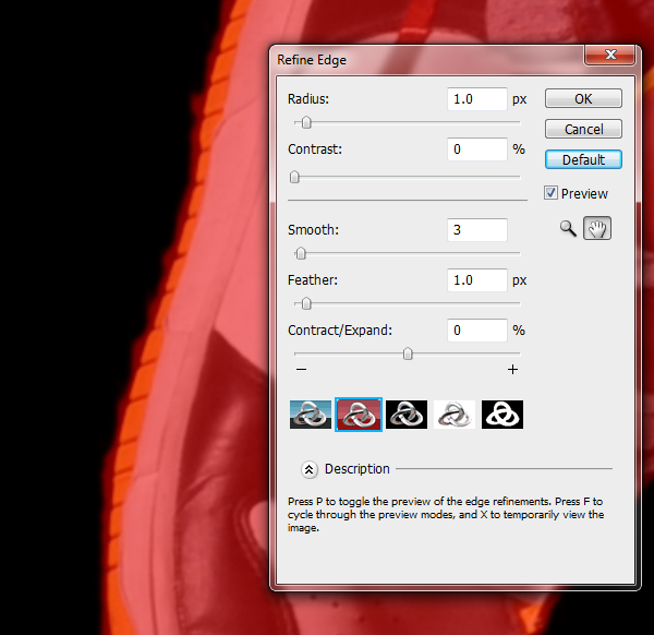
If you’re using Photoshop CS3 or newer, you can use the refine edge tool to enhance the selection. Simply select any one of the selection tools then click on the “Refine Edge” button on the option bar.
![]()
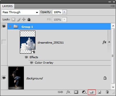
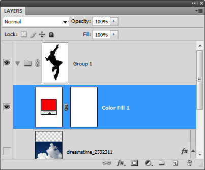
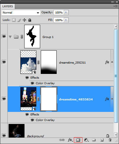
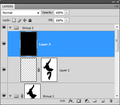
Step 5 – Create a layer mask of the selection on a group
By applying the mask in a group instead of a layer, we can simply place any layer we want in this group and it will only be visible behind the model. This saves us from having unnecessary layer masks.
Select the layer of the clouds then click on the ![]() button in the layers palette.
button in the layers palette.
With the group selected, click on the ![]() button to add a layer mask. It will automatically apply your selected area into the layer mask. Anything we put inside this group will appear around the model.
button to add a layer mask. It will automatically apply your selected area into the layer mask. Anything we put inside this group will appear around the model.
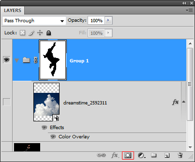
Now we’ll check to see if there are any flaws to the mask. Add a color fill layer with a contrasting color such a red. To do this, select the layer with the clouds then choose Layer > New Fill Layer > Solid Color.
Step 6 – Refine the layer mask
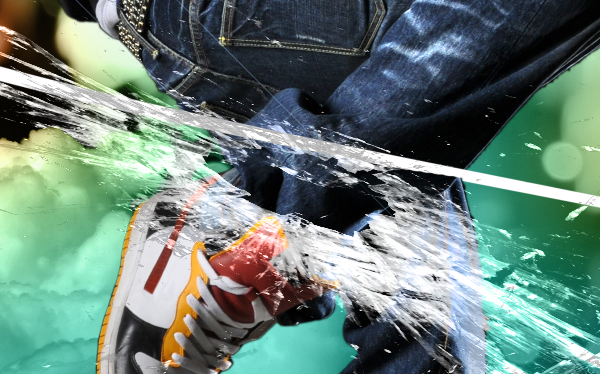
Zoom into 100% view to find any flaws such as this one on the shoe.
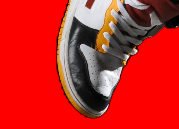
Select the layer mask in the layer palette then use the brush and eraser to refine the edges. Use the brush tool to erase the background or the eraser tool to add. In the option bar of the brush and eraser tool, you can change the brush hardness. Use a hardness of 50% or more for sharper edges.
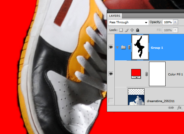
When you’re done refining the mask, you can delete the color fill layer and make the layer with the clouds visible.
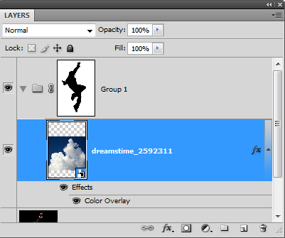
Step 7 – Complete the blending of the clouds
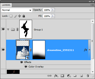
Add a layer mask to the layer with the clouds. To do this, select the layer then choose Layer > Layer Mask > Reveal All.
Select the eraser tool. Right click anywhere in the document window to bring up the brush options. Use a very large brush size with a hardness of 0%.

Make sure that the layer mask of the cloud layer is selected. To select the layer mask, click on the layer mask thumbnail in the layers palette. It should have a border around the layer mask to indicate that it is selected. With the eraser tool, erase the bottom of the clouds so that it fades gradually.
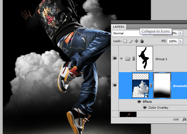
Select the move tool then move the clouds lower so that it is just above the spotlight.
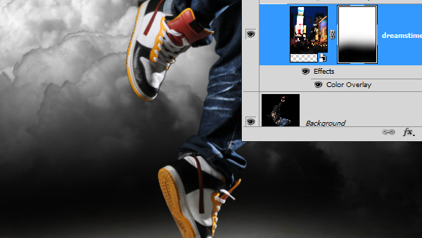
Step 8 - Place the city background
Before you can use the place command, you need to have the layer mask deselected. Click on the layer thumbnail of the clouds layer to deselect the layer mask.
Choose File > Place. Browse for the photo of the city then click OK. Scale and position the image like shown below then press enter on your keyboard to apply the changes.
Move the layer with the city background below the layer with the clouds.
Step 9 – Desaturate the city background
First, we’ll make the layer grayscale using the same technique we used earlier with the clouds layer. Right click on the layer of the city background then choose blending options.
Apply the settings as shown below then click OK.
Step 10 – Fade the bottom edge of the layer with the city background
If you look closely at the bottom of the city edge layer there is a hard edge. To fix this, we’ll fade the edge with a layer mask.
With the layer of the city background selected, click on the ![]() to add a layer mask.
to add a layer mask.
Select the eraser tool then right click anywhere in the document window. Use a large brush with a hardness of 0%.

Make sure that your layer mask is selected. It should have a white border around the layer mask thumbnail to indicate that it is selected. With the eraser tool, erase the bottom of the edge so that the hard edge is gone.
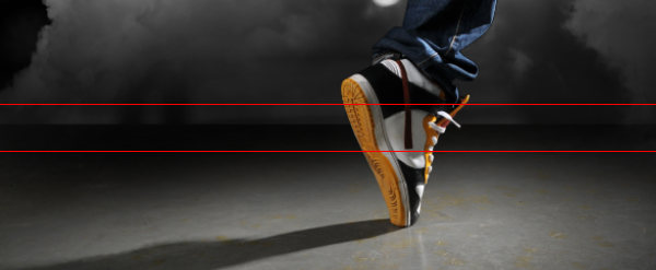
Here’s the before and after of fading the bottom edge.
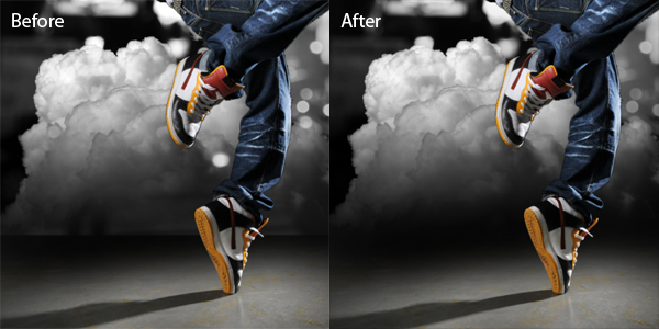
Here’s what our image looks like so far.

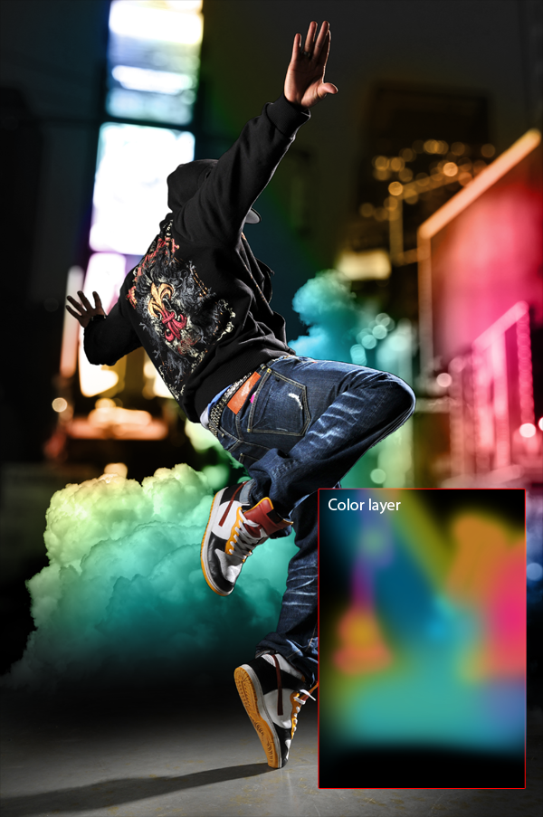
Step 11 – Add abstract colors to the background
Create a new layer above the clouds layer then set the blending mode to color. Now we can paint in this layer with any color and it will only affect the color of the layers below.
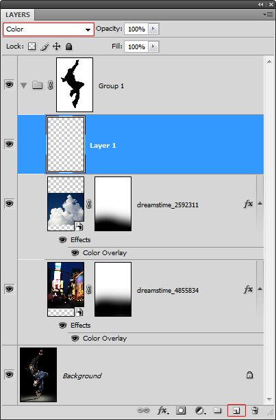
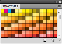
In the swatches palette (Window > Swatches), click on the ![]() menu then choose any one of the PANTONE CMYK swatches.
menu then choose any one of the PANTONE CMYK swatches.
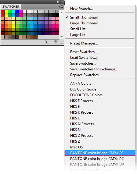
Now you have the yellow, magenta, and cyan colors easily accessible form your swatches palette.
Select the brush tool. On the option bar at the top, you can select the brush size, hardness, and opacity. I recommend starting with a 50% opacity to paint.
Select any of the first three colors in the swatches palette then begin painting.
You can overlap two colors to create other colors such as teal. Remember that you can adjust the size, hardness, and opacity of your brush for different results. Here is what we ended up with and how we got the results.
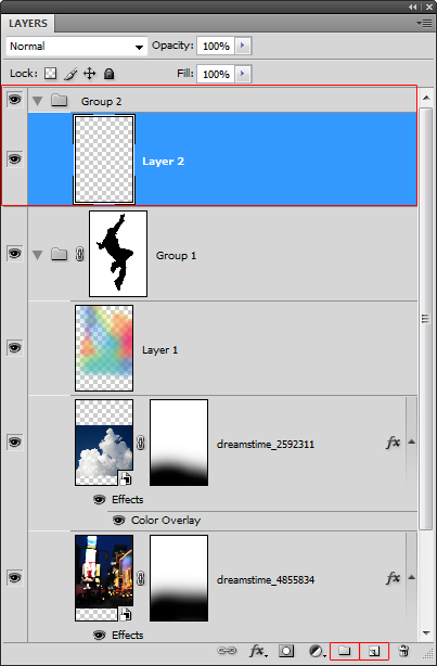
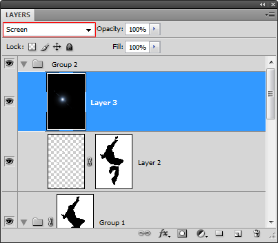
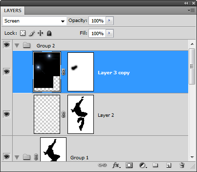
Step 12 – Add a swirling beam of light
Create a new layer inside a new group. This group will be used to store all the special effects we’ll be adding on later. Select Group 1 then click on the ![]() button to create a new group above it. Then, click on the
button to create a new group above it. Then, click on the ![]() button to add a new layer inside Group 2.
button to add a new layer inside Group 2.
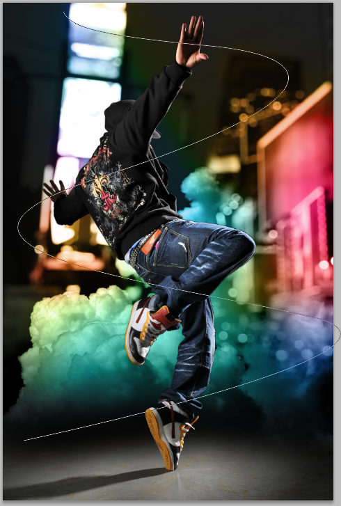
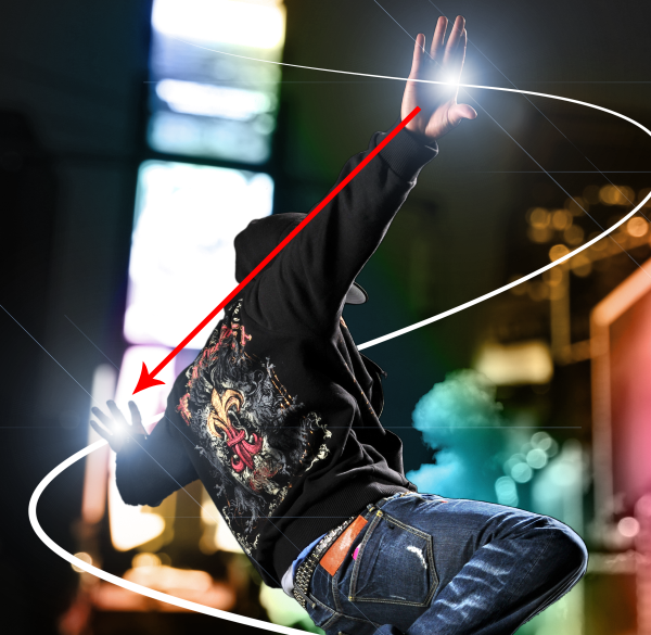
Select the pen tool then apply the settings in the option bar as shown in the image below.

Create a curved path similar to the image below.
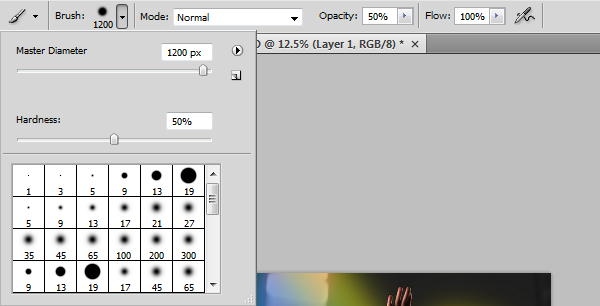
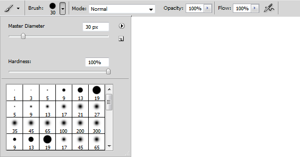
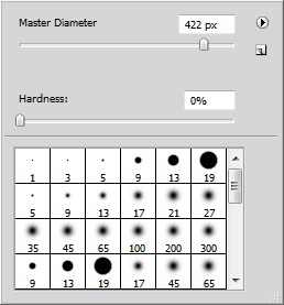
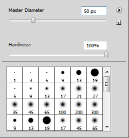
Select the brush tool and adjust the settings. Use the settings as shown below but adjust the master diameter setting to change the size of the brush. The size of this brush will determine the thickness of the beam of light. We used a brush size of 30 px on the high resolution file used for this tutorial. But if you are working on a low resolution file (ex. 800 x 600 pixels), then you should use a smaller brush size such as 7 pixels.
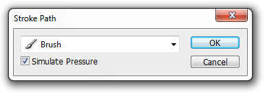
Make sure that you have the new layer in Group 2 selected. In the paths palette (Window > Paths), right click on the work path then choose stroke path.
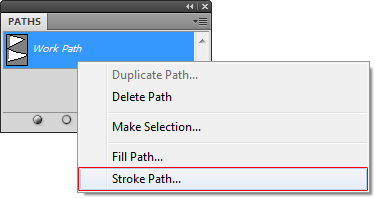
In the stroke path dialog, select brush from the drop down menu and enable simulate pressure.
This is what our image looks like so far with the swirling beam of light. However, it doesn’t look like it is swirling around the model. In the next step, we’ll mask out certain areas to make it look like it is swirling around the model.

Step 13 – Create a mask for the swirling beam of light
Hold down the Ctrl key on your keyboard then click on the layer mask of group one.
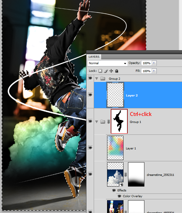
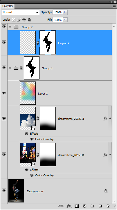
Select the layer with the beam of light then click on the ![]() button to add a layer mask. It should apply the selected area as the layer mask.
button to add a layer mask. It should apply the selected area as the layer mask.
Make sure that you have the new layer mask selected. Select the brush tool the paint in white over the areas shown in the image below. This will make the beam of light look like it is swirling around the model.
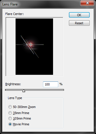
Step 14 – Create a lens flare
Create a new layer as the top layer in Group 2 then fill it with black.
Choose Filter > Render > Lens Flare. Set the brightness to 100% and choose movie prime as the lens type. Adjust the flare center to get a flare that you like then click OK.
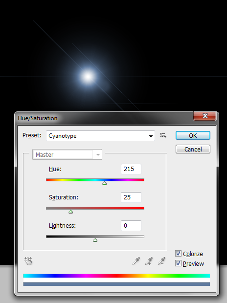
Choose Image > Adjustments > Hue/Saturation then apply the settings as shown below. If you are using Photoshop CS3 or older, enable the colorize option first then adjust the hue and saturation settings.
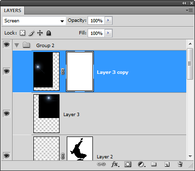
Step 14 – Duplicate and position the lens flare
First, change the blend mode of the lens flare layer to screen.
Select the move tool then reposition the lens flare to models right top hand.

While holding down the Alt key on your keyboard, drag the lens flare to the models left hand. This will create a duplicate of the lens flare.
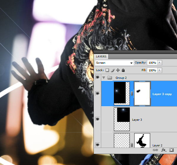
Step 15 – Mask the lens flare
We want to make the second lens flare appear as behind the models hand. To do this, we’ll mask it out using a layer mask. Click on the ![]() button to add a layer mask.
button to add a layer mask.
Select the eraser tool then use a large brush with 0% hardness.
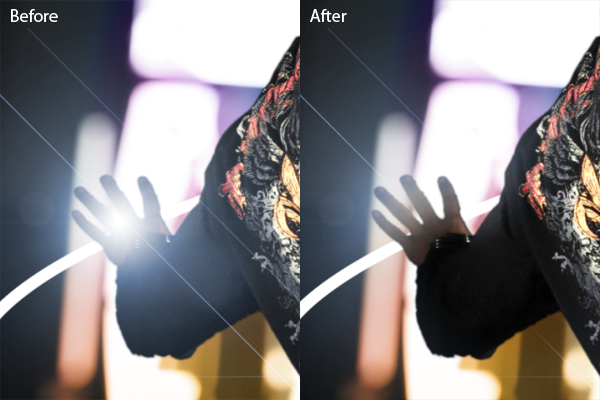
Erase over the hand and arm so that the lens flare looks like it is behind the hand.
Here’s the before and after results.
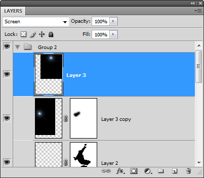
Step 16 – Merge the lens flare layers
Because we will not need to reposition the lens flare anymore, we can merge them together. If you simply merge the two layers right now, the layer mask will be lost. To preserve the layer mask, move the layer without the layer mask up so that it is on the top. Then, choose Layer > Merge Down or Ctrl+E.
A dialog will appear asking if you want to apply or preserve the layer mask. Select preserve.
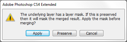
Now the two layers are merged and the layer mask is still there.
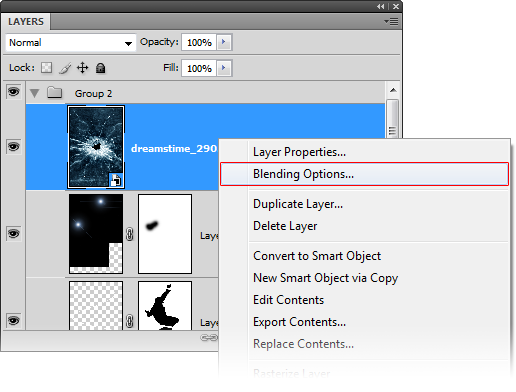
Step 17 – Import the image of the shattered glass
Choose File > Place, browse for the image of the shattered glass, then click OK. Press enter on your keyboard to exit out of the transform tool.
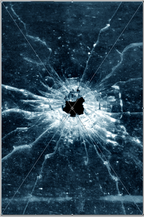
Step 18 – Add transparency to the glass layer
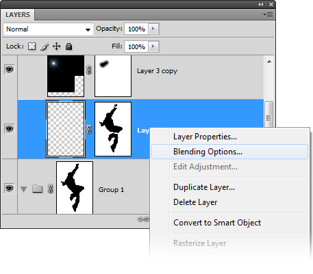
Using the same technique used earlier, we’ll make the dark area of the layer transparent so that it blends into the photo. Right click on the layer with the glass then choose Blending Options.
At the bottom of the window in the blend if options, drag the black input sliders towards the right until the background disappears.
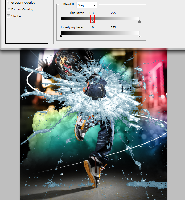
Hold the Alt key on your keyboard then drag the right black input slider towards the right until the edges are softened.
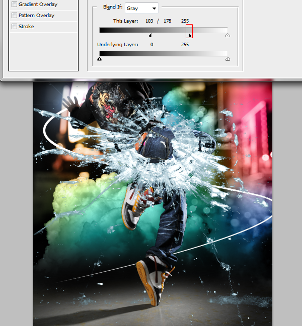
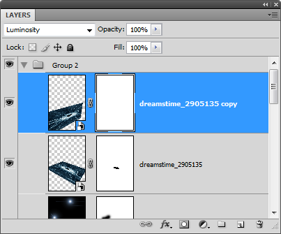
Change the blending mode of the current layer to luminosity. This will allow the color from the layers below to be seen through the glass.
Step 19 – Prepare the layers
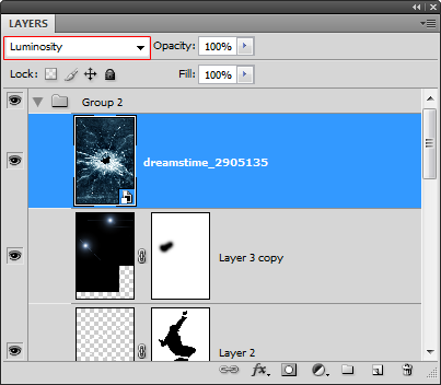
Duplicate the layer with the glass (Layer > Duplicate Layer)

Hide the other layer by clicking on the ![]() icon.
icon.
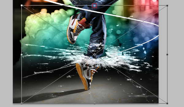
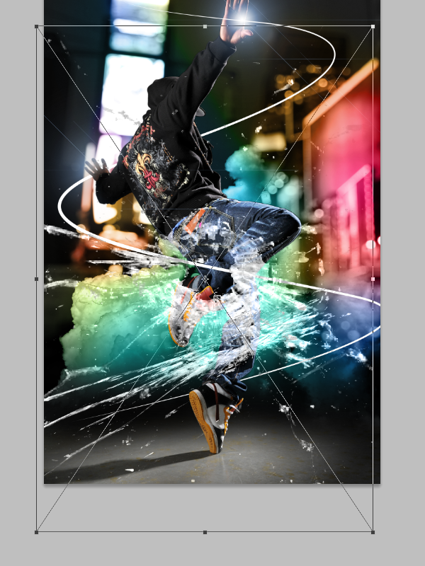
Step 20 – Distort the first glass layer
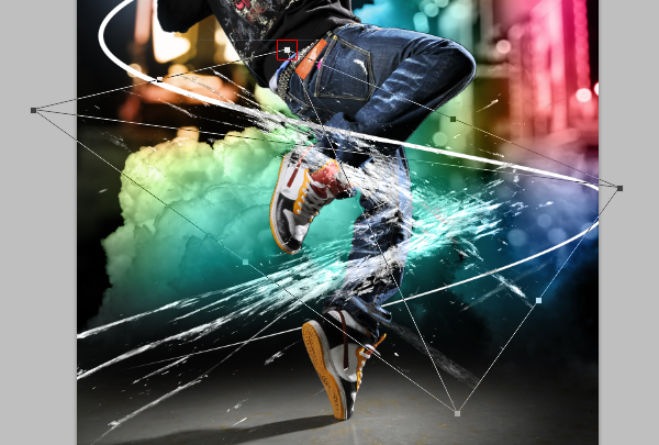
With the current glass layer selected, choose Edit > Free Transform to use the transform tool. Hold down your left mouse button anywhere inside the boundary border then drag it to the models left ankle.
While holding down the Alt key on your keyboard, drag the upper middle handle downwards so that your shattered glass looks like the image below.
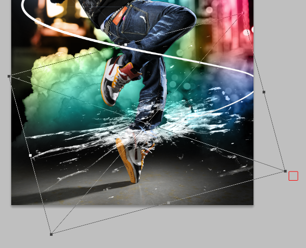
Rotate the layer like shown below. To rotate, position your cursor outside the bounding border then drag to rotate.
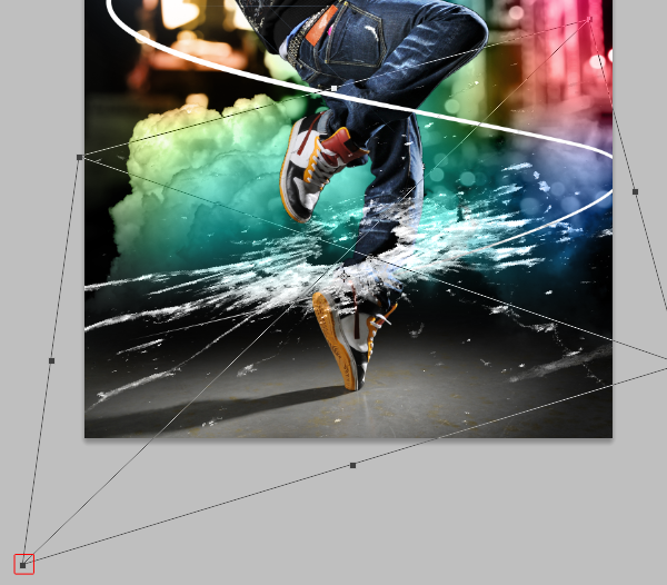
While holding down the Ctrl key on your keyboard, drag the bottom left handle towards the bottom left like shown below.
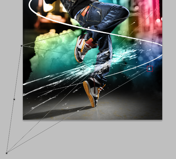
While holding down the Ctrl key, drag the bottom right handle towards the upper left like shown below. Press enter on your keyboard to apply the changes.
Step 21 – Distort the second glass layer
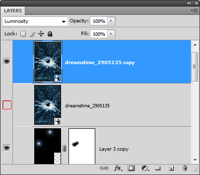
Select the other shattered glass layer then enable back the visibility by clicking where the ![]() icon should be.
icon should be.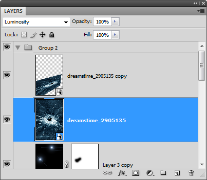
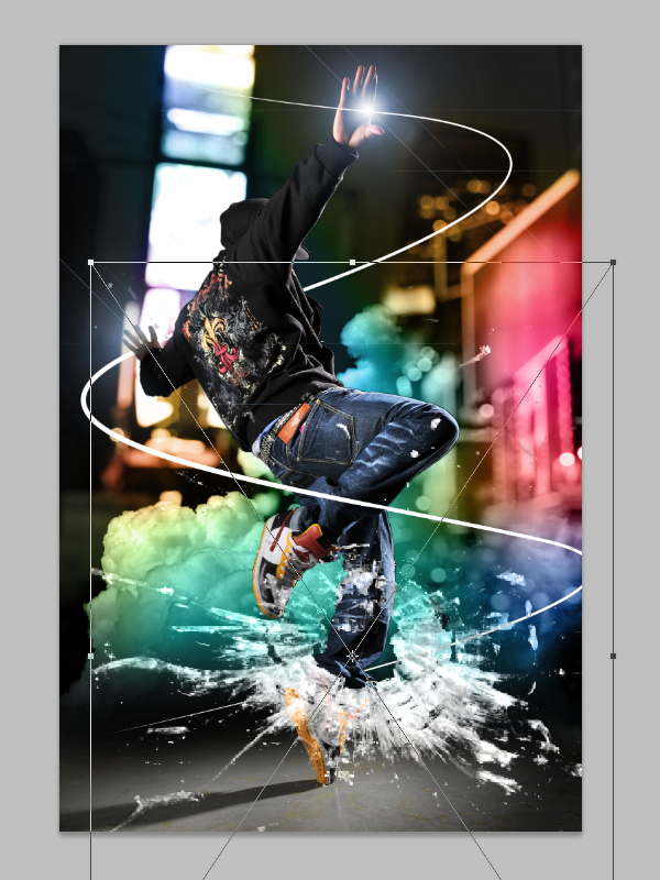
Like before, we’ll use the transform tool to distort the layer. Choose Edit > Free Transform then position the center of the shattered glass at the models other ankle.
While holding down the alt key, drag the upper middle handle towards the bottom to shrink the layer like shown in the image below.
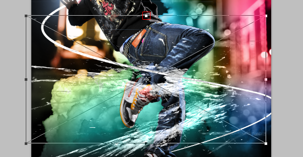
Rotate the layer like shown below by clicking anywhere outside the boundary border and dragging.
While holding down the Ctrl key on your keyboard, drag the top left corner downwards. Press enter on your keyboard to apply the changes.
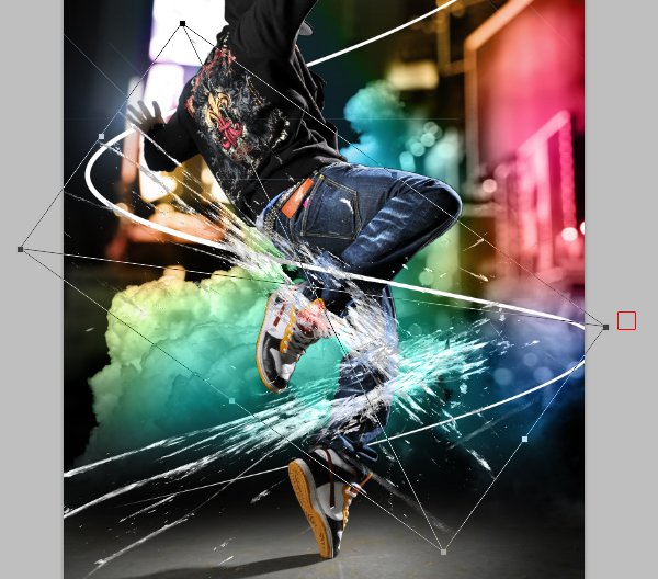
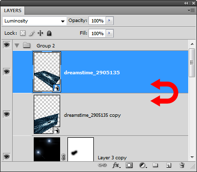
Step 22 – Swap the layers
Switch the position of the two shattered glass layers. Move the bottom one above the top one. This is because the shattered glass on the models left ankle is supposed to appear in front of his left ankle.
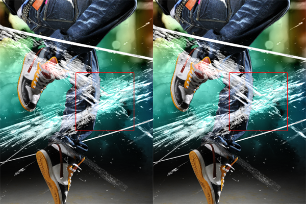
Here’s a before and after comparison of switching the layers. You can see that the shattered glass doesn’t appear to be wrapping around the models legs. We’ll fix this with a layer mask in the next step.
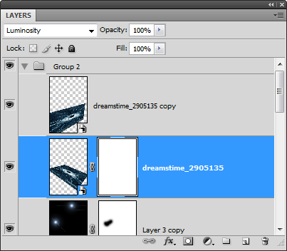
Step 23 – Add masks to the shattered glass layers
Select the second layer with the shattered glass then click on the ![]() button to add a layer mask.
button to add a layer mask.
Zoom in to 100% and use the move tool to position the center of the shattered glass on the leg.
Select the eraser tool, right click anywhere in the document window, then set the hardness to 100%.
Erase the upper part of the shattered glass that touches the leg and the beam of light like shown below. Now it looks like the shattered glass is wrapped around the leg but not in front of the beam of light.

We’ll repeat this for the other leg. Select the other layer then click on the ![]() to add a layer mask.
to add a layer mask.
Like before, erase the upper area of the shattered glass that touches the leg as shown below.

Step 24 – Make the beam of light glow
To finish this photo manipulation, we’ll make the swirling beam of light glow. Right click on the layer with the beam of light then choose blending options.
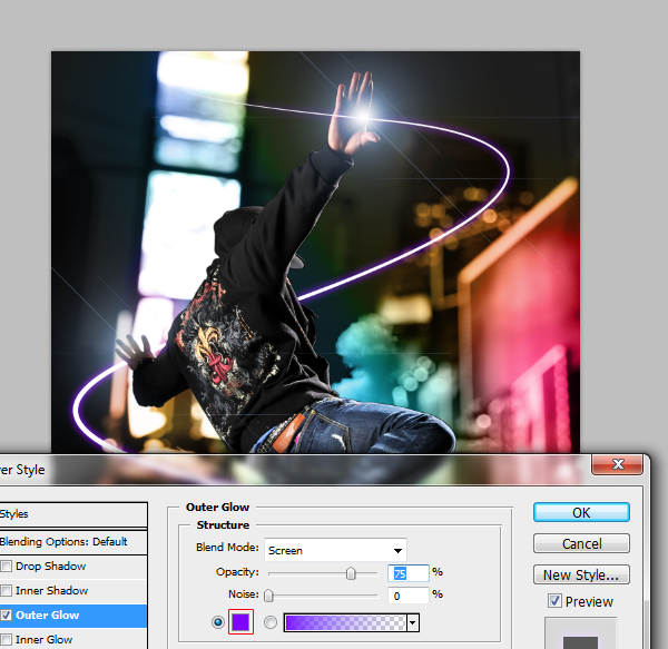
Select the outer glow layer style then adjust the size until you see a glow on the beam of light.
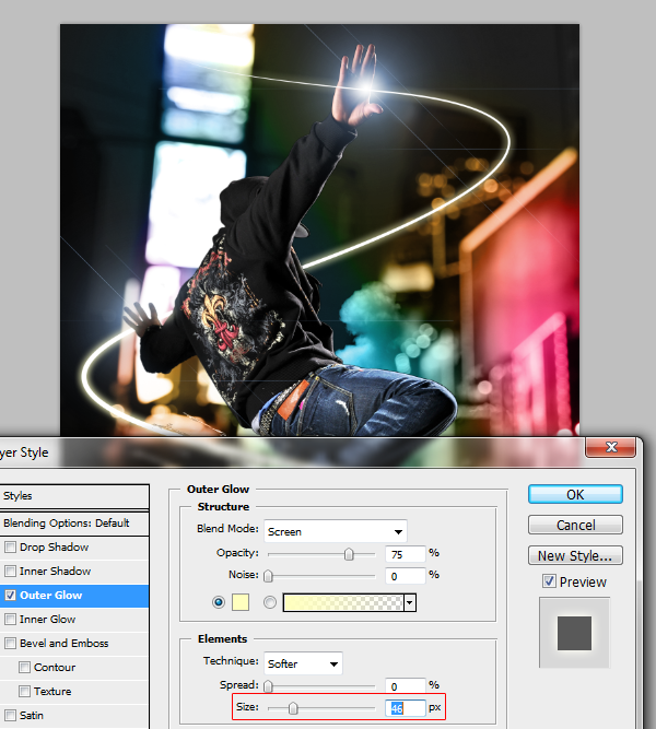
Select a color that you like for the glow.
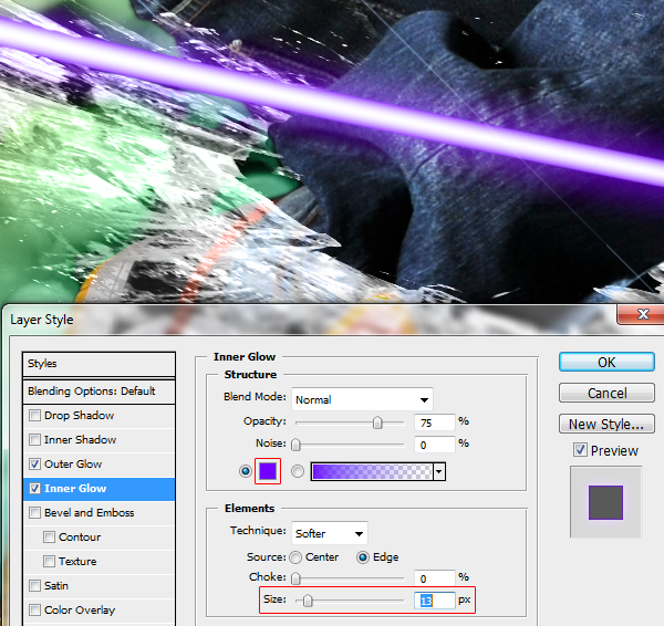
Next, enable the inner glow layer style and zoom in so that you can see the beam of light. Press Ctrl+ to zoom in and drag in the document window to reposition. Set the blend mode to normal.
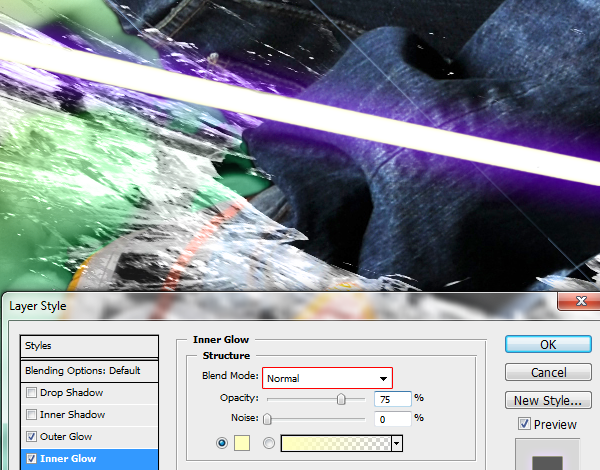
Set the color to the same or similar color you used in your outer glow layer style then adjust the size so that the inner glow is more visible.
Final Results
11:36:00 AM

Adding a stroke to some text in Adobe
Preview of Final Results

Double and Triple Strokes Photoshop Tutorial
Step 1
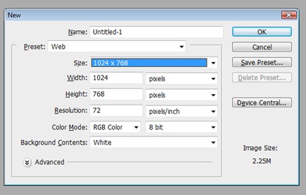
Open Photoshop and go to File>New for a new file at this size and click OK.
Step 2
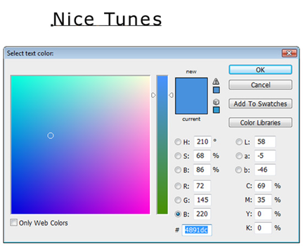
Click the Text tool in the toolbar and click anywhere and type in some text. Don't click-and-drag a text box, but instead just click once and then type so we can click-and-drag a corner to resize it later. I set the color of mine to #4891dc by highlighting the text and then clicking the color on the Options palette.
Step 3
Change the font to something that will look good with strokes, such as an san serif font (arial or verdana instead of times new roman). I set it to Maiandra GD. Then click the Move tool and click-and-drag a corner to make it a little bit bigger. Remember to hold Shift to maintain proportion. After resizing, press Return (PC: Enter) to apply resize.

Step 4
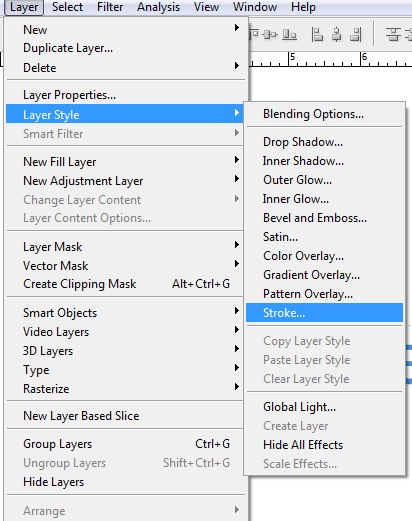
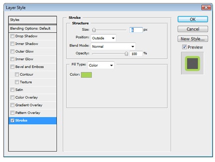
Go to Layer>Layer Style>Stroke.
Step 5
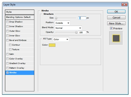
The Position should be set to Outside and set the size to 3. Change the color to one that looks good with the original text color.
Step 6
It should look something like this, depending on the colors you selected.

Step 7
Now if we went to Layer>Layer Style>Stroke again, we'd just bring up the options to edit the original stroke. Instead, click-and-drag the text layer to the New Layer icon the Layers palette (or press Command-J (PC: Control-J)). This duplicates the text layer.

Step 8
Now we need to edit the stroke on the lower, original text layer to make it larger. Double-click on the Stroke effect listed on the bottom text layer.
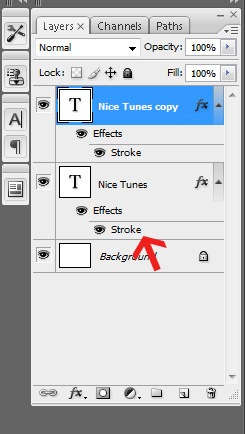
Set the size to something larger, such as 6 pixels, and change the color to something that looks good with the other two colors. You could use Adobe
Step 10
It should look something like this.

Step 11
Repeat the steps of duplicating a layer and changing the size and color of the stroke to add a third, fourth, or fifth stroke. Remember to edit the lower layer when wanting to make the stroke larger to show past the layer on top of it. Click-and-drag a layer below another if they get arrange in the wrong order. In this example, I gradually went from a royal blue to a different hue blue, creating a retro gradient.

Step 12
Of course, each stroke doesn't have to have a color, just one to hide the color behind it. Try setting the first stroke to white, and then setting the second stroke to the same color as the text by hovering over the text when selecting the color (it will convert to an Eyedropper tool).
11:24:00 AM
DICOM is the industry standard format for medical scans. Learn how DICOM files are used with Adobe
Opening DICOM Files
To open DICOM files, open the File menu and choose Open. Browse for the DICOM file and click Open.
Open.
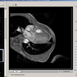
Once you click Open, a window will appear with settings you can modify.
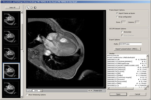
Options
Frames
On the left, you can select which frame to view and open. To open a single frame, select the frame and click open. To select more than one, hold the CTRL key and click. To select all the frames, click the Select All button.
DICOM Dataset Options
There are two options in this area you can modify
Anonymize
Checking this option will anonymize the file by replacing all patients metadata with "anonymize".
Show Overlays
If your file has overlays such as annotations, curves, or text, you can check this box to display those overlays.
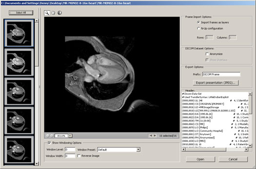
Windowing
Windowing lets you adjust the brightness and contrast of the image. To view all the Windowing options, check the Show Windowing Options checkbox located below the image.
Presets
There are 5 presets you can choose from:- Default
- Lung
- Bone
- Abdomen
- Full
Manual Adjustments
Or, you can manually adjust the settings using your mouse:
- Click on the
 button to select the Window Level tool.
 - Click on the middle of the image and drag the tool up or down to adjust the level.
- Drag the tool left or right to adjust the width.
Reverse Image
To reverse the image, simply check the Reverse Image checkbox.
Frame Import Options
This area lets you choose how you would like to open the images.
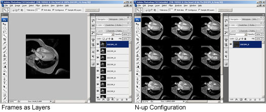

Import frames as layers
This option will import frames into layers. This option is useful for manipulating the image or creating an animation.
N-up Configuration
This option will tile the frames onto one layer. Select this option if you would like to print the frames onto transparencies.
{mospagebreak title=Creating an Animation}Creating an Animation
Step 1
Open a DICOM file. Open the File menu and select Open. Browse for a DICOM file (.dc3, .dcm, .dic, or no extension) and click OK
Step 2
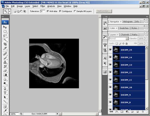
Press the Select All button to select all the frames. In the Frame Import Options, choose Import frames as layers. Apply any other settings needed then click OK.
Step 3
You should now have each frame as layers. Select all the layers by pressing Alt+Ctrl+A or going into the Select menu and choosing All Layers.
Step 4
Open the Animation window by going into the Window menu and selecting Animation.
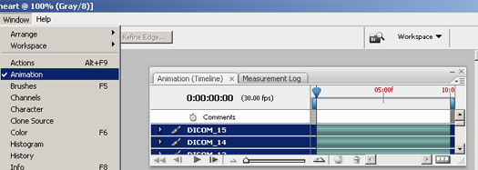
Step 5
In the Animation pallet, click on the ![]() button located near the top right to open the flyout menu. In the flyout menu, select Make Frames From Layers.
button located near the top right to open the flyout menu. In the flyout menu, select Make Frames From Layers.
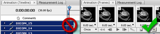
Step 6
If the Animation window is not in Frame view, press the  button to convert the animation into a frame animation. If it's already in frame view, you can skip this step.
Step 7
Now we need to set how many times it should loop. Click on the bottom right menu to select how the animation should loop. To have the animation loop forever, select Forever.
Step 8
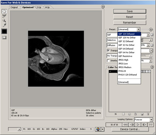
To save the animation as an animated GIF file, use the Save for Web & Devices tool. To open the Save for Web & Devices tool, press Shift+Ctrl+S or open the File menu and select Save for Web & Devices. In the Save for Web & Devices tool, Select a GIF preset and modify the settings if necessary. Click the Save button when you are ready to save.
Final Results
Measuring
We can use the measurement tool to measure parts in the medical image.
Step 1
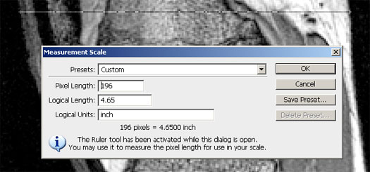
First, we need to set the measurement scale. To do this, we need to know the measurement of one part in the image. For this photo of a knee, the thickness of the knee was measured as 4.65 inch. To set the measurement scale with this data, go into the Analysis>Set Measurement Scale menu and select Custom. When the Measurement Scale window appears, draw a line on the image to indicate the area you would like to set the measurement for. For this image of a knee, I drew a horizontal line across the entire width of the knee. Next, enter in the Logical Length and Logical Units field the measurement. For this image, the knee was measured to be 4.65 inch so I entered 4.65 in the Logical Length field and inch in the Logical Units field. Click OK when done.
Step 2
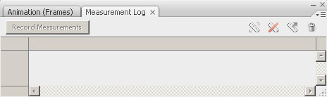
Open the Measurement Log window by going into the Window and selecting Measurement Log.
Step 3
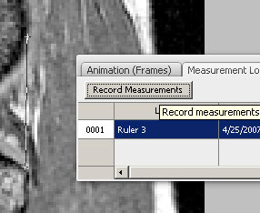
Now, select the Measurement tool from the tool bar or by going into the Analysis menu and selecting Ruler Tool. Draw a line indicating the area you would like to measure and click the Record Measurements button in the Measurement Log window. The data is now recorded in the Measurement Log.
3:03:00 PM
The Mono Project's MonoDevelop is a full IDE for developing C# programs under the Mono runtime. If you’ve worked with Microsoft Visual Studio, you will see many similarities in MonoDevelop and will feel quite comfortable in the Mono environment. If you’re new to MonoDevelop and haven’t worked in Visual Studio, you’ll find that the learning curve is not very steep.
The Mono Project recently released Version 2.0 of MonoDevelop, a full IDE for developing C# programs under the Mono runtime.
The short story is that if you’ve worked with Microsoft Visual Studio, you will see many similarities in MonoDevelop and will feel quite comfortable in the Mono environment. If you’re new to MonoDevelop and haven’t worked in Visual Studio, you’ll find that the learning curve is not very steep.
One important change in Version 2.0 is the use of the MSBuild file format. Since Mono is an open-source implementation of Microsoft’s .NET runtime, it makes sense to support as many .NET tools and formats as possible.
As somebody who has been faced with porting from Visual Studio to Linux and other operating systems, I can say that one of the biggest frustrations is the build process. With Visual Studio’s proprietary build file formats (which are similar to make files, but not at all compatible with the standard make utilities), the support for MSBuild file formats is a welcome addition to MonoDevelop.
Another new feature is the way in which solutions are handled. Previously, MonoDevelop used nested solutions, but now, to be more compatible with Visual Studio’s solution system, MonoDevelop allows you to organize projects as folders within a solution.
In addition to many other improvements—such as per-project policies and opening multiple solutions simultaneously (something you can’t do in Visual Studio)—MonoDevelop now includes a powerful assembly browser. This tool is particularly useful for its ability to let you inspect the contents of an assembly, right down to the IL, including types and member definitions.
Originally, Mono did not support ASP.NET, but it wasn’t long before support was added. Now, as the support has become stronger and more complete, MonoDevelop has been enhanced to offer full support for ASP.NET. For example, the Web projects (which are handled differently than non-Web projects within Visual Studio) are compatible with Visual Studio 2008, including Visual Web Developer. Again, this will make porting much easier.
Of course, MonoDevelop is for Linux, and, as such, it caters to the needs of the typical Linux developer. For example, the editor in MonoDevelop has almost full vi support, including most of the common vi commands.
Although many of us who work primarily in Visual Studio are perfectly comfortable with the Visual Studio editor, I personally know many Linux and Unix developers who are much more at-home with the vi editor. (And I, for one, can attest that once you learn vi, you never forget it.) So even though vi often gets a bad rap as being archaic, it’s fast and efficient when you know what you’re doing. This is a welcome addition to MonoDevelop.
Next, and this is a biggie, MonoDevelop now has full GUI support for debugging, both with MDB (Mono Debugger) and the standard GDB support. You can set breakpoints within the IDE, and step through your code, inspect and evaluate expressions, and more.
In short, MonoDevelop Version 2.0 is a fine tool that is on par with Visual Studio and offers many features beyond those that I’ve listed here. These include a split-view code editor; incremental search bar (something many of us love once we start using it); and code folding. You can see the whole list of improvements at http://monodevelop.com/Download/MonoDevelop_2.0_Released.
Finally, you’ll want to be aware of one shortcoming: Right now, MonoDevelop is available only on Linux and Mac OS X, not Windows. However, this is temporary; a team within the Mono project is actively working on porting it to Windows. You’ll want to keep an eye on the main page at monodevelop.com for more information.
ReadMore...